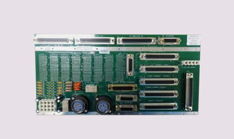
AMAT 0100-01577 PCB, Step/Direction Motor Interface
AMAT 0100-01577 is a high-performance Step/Direction Motor Interface PCB manufactured for Applied Materials.
This board serves as a vital communication and control link within the motion control subsystem of 200mm and 300mm semiconductor fabrication tools.
It is specifically designed to bridge the gap between the high-level system controller and the localized motor drivers that move wafer handling robots, slit valves, and lift mechanisms.
Technical Parameter Table
| Parameter | Specification |
| Manufacturer | Applied Materials (AMAT) |
| Part Number | 0100-01577 |
| Description | PCB, Step/Direction Motor Interface |
| Function | Motion Logic & Signal Routing |
| Interface Type | VMEbus / Multi-pin Ribbon Connector |
| Signal Logic | Differential Step/Dir (Pulse/Direction) |
| Compatibility | AMAT Centura, Endura, Precision 5000 (P5000) |
| Weight | Approx. 0.95 kg |
Related Models
The 0100-01577 is typically found in the VME rack or electronics tower alongside:
0100-00003: Stepper Drive Controller Board.
0100-00011: Chopper Drive PWB.
0100-01130: Sensor Interface PCB.
0100-01578: Often a complementary revision or secondary axis interface.
Application Cases
This interface board is critical for the “mechanical choreography” of a semiconductor tool:
Wafer Transfer Robots: Managing the pulse-train signals required for the smooth extension (R), rotation (Theta), and vertical (Z) movement of the robot arms.
Slit Valve Actuation: Coordinating the precise timing for opening and closing vacuum isolation valves between process chambers.
Susceptor/Heater Lifts: Controlling the stepper motors that raise and lower the wafer pedestal to the exact processing height.
Load Lock Indexing: Driving the vertical lift pins that facilitate the transition of wafers from atmospheric pressure to high vacuum.
Product Advantages and Features
Signal Integrity: Uses advanced differential signaling to eliminate electromagnetic interference (EMI), which is common in high-power plasma environments.
Deterministic Timing: Ensures zero-latency communication between the CPU and the motor, preventing “step loss” during high-speed robotic movements.
Fault Isolation: Features onboard status LEDs that allow technicians to immediately see if the “Step” or “Direction” pulses are being generated by the controller.
High Compatibility: Designed to work across multiple generations of AMAT mainframes, making it a versatile “universal” spare part for many 200mm fabs.
Other Models in the Same Series
0100-015xx Series: This series focuses on the transition from simple analog motor control to more sophisticated digital pulse-width modulation (PWM) and Step/Dir logic.
0190-00xxx Series: Later 300mm “Bridge” boards that eventually replaced some functions of the 0100-01577 in newer toolsets.
Installation and Maintenance
Installation: Power down the system before removal. The board is sensitive to Electrostatic Discharge (ESD); always use a grounded wrist strap. Ensure the ribbon cables are fully seated and the locking clips are engaged to prevent intermittent signal loss.
DIP Switch Configuration: Check the back or side of the board for DIP switches that define the axis address. These must match the original board being replaced.
Maintenance: Visually inspect for “heat stress” around the driver ICs. If the robot experiences “hunting” (vibrating without moving), check the Step/Dir output pins on this board for consistent voltage levels.
Unique Product Description
The AMAT 0100-01577 is the “signal conductor” for the tool’s physical movements.
In a semiconductor fab, where a movement error of just one millimeter can result in thousands of dollars in lost silicon, this board provides the sub-micron precision required for modern manufacturing.
It is a cornerstone of the Step/Direction architecture, ensuring that the commands from the tool’s “brain” are flawlessly executed by its “muscles.”