Woodward easYgen-3000 Genset Control for
easYgen-3000
Genset Control for
Multiple Unit Operation
The easYgen-3000 is a control unit for genset management applications. The numerous inputs and outputs,
along with a modular software structure, permit you to use the easYgen-3000 for a wide range of applications
with only a single part number. This includes stand-by, AMF, peak shaving, import-export, cogeneration or
distributed generation, among others. Also the easYgen-3000 is compatible for island, island parallel, mains
parallel and multiple unit mains parallel operations.
The easYgen-3000 is able to control up to 32 gensets connected in a network with automatic sequencing.
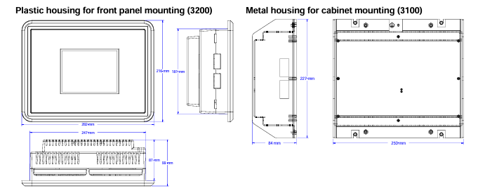
The easYgen-3000 is available in two variants, the easYgen-3100 for cabinet back panel installation, and the
easYgen-3200 with graphical display and soft keys for front panel mounting.
FlexAppTM – This feature provides the tools to easily configure the number of operated breakers: None, GCB,
GCB and MCB.
LogicsManagerTM – Woodward’s LogicsManager software enables to change the operation sequences and
adapt them to specific needs. The LogicsManager accomplishes this by monitoring a range of measuring val
ues and internal states, which are combined logically with Boolean operators and programmable timers. This
enables to create and/or modify control and relay functions.

easYgen-3000
FlexInTM – The analog inputs are configurable to operate with VDO, resistive, and/or 0 to 20 mA senders.
Flexible Outputs – Speed and voltage bias outputs are configurable to function with all speed governors and
voltage regulators. The outputs can also be used as freely scalable outputs (e.g. for driving external meters).
FlexCANTM – Advanced network interfaces ensure unsurpassed control performance – from engine control up
to total plant operation. The easYgen-3000 is capable of working with all common industrial interfaces, includ
ing CAN, RS-232. and RS-485. The multiple communication protocols permit the easYgen-3000 to communi
cate with a vast majority of engine control units (ECUs), external I/O boards, PLCs, and modems. CANopen,
J1939. Modbus RTU, and Modem protocols are supported.
DynamicsLCDTM – The adaptive and interactive 5.7″, 320×240 pixel graphical LC display with soft keys and a
clear menu structure ensures intuitive user operation and navigation.
Features
easYgen-3000
• Operation modes: Auto, Stop, Manual, and Load/No Load test modes via discrete input possible
• Breaker control: Slip frequency / phase matching synchronization, open-close control, breaker monitoring
• Load transfer features: open / closed transition, interchange, soft loading / soft unloading, mains parallel
• Process and load-dependent start/stop logic for diesel and gas engines programmable for spinning or system
reserve with fixed or dynamic priorities.
• Real and reactive power load sharing with up to 32 units
• Remote control via interface and discrete/analog inputs for adjusting speed, frequency, voltage, power, reactive
power, and power factor set points
• Complete integrated engine and generator protection as well as mains monitoring features
• Freely configurable PID controllers for various control purposes, such as heating circuit control (CHP applica
tions), water level, fuel level, or pressure and/or other process values
• Special Scania S6. MTU ADEC, Volvo EMS2 & EDC4. Deutz EMR2. MAN MFR/EDC7. SISU EEM and Wood
ward EGS02 ECU support (depending on Package)
• Counters for operating hours / engine starts / maintenance / active energy / reactive energy
• Configurable trip levels / delay timers / alarm classes for monitoring and protective functions
• Clear text display and evaluation of up to 100 J1939 analog values
• Discrete and analog I/O expansion board connectivity (Woodward IKD 1 or Phoenix Contact IL series)
• Front panel and PC configurable (ToolKit software)
• Multi-level password protection for access via HMI or interface
• Multi-lingual capability (English, German, French, Spanish, Chinese, Japanese, Italian, Portuguese, Turkish, Russian)
• Peak shaving operation
• Stand-by operation
• AMF operation
• Cogeneration (CHP)
• Isolated & mains parallel
operation
• Import/export control
• Soft loading features
• Open/closed transition
• Load sharing and load
dependent start/stop for
up to 32 units
• Programmable operation
sequences
• Multi-lingual capability
• CANopen / J1939 ECU
Control
• Modbus RTU Protocol
• CE marked
• UL/cUL Listing
• LR & ABS Marine Ap
provals
• Event recorder (300 events, FIFO) with real time clock
Power supply …………………………………………………. 12/24 Vdc (8 to 40 Vdc)
Intrinsic consumption ………………………………………………………… max. 17 W
Ambient temperature (operation) ………………….. -20 to 70 °C / -4 to 158 °F
Ambient temperature (storage) …………………… -30 to 80 °C / -22 to 176 °F
Ambient humidity ……………………………………………… 95 %, non-condensing
Voltage ………………………………………………………………………………….. ( /Δ)
100 Vac [1] Rated (Vrated) …………………………………….. 69/120 Vac
Max. value (Vmax) ……………………………………. 86/150 Vac
Rated surge volt.(Vsurge) ……………………………………………. 2.5 kV
and 400 Vac [4] Rated (Vrated) …………………………………… 277/480 Vac
Max. value (Vmax) ………………………………….. 346/600 Vac
Rated surge volt.(Vsurge) ……………………………………………. 4.0 kV
Accuracy ……………………………………………………………………………… Class 1
Measurable alternator windings ………………… 3p-3w, 3p-4w, 1p-2w, 1p-3w
Setting range ………………… primary ……………………………50 to 650.000 Vac
Linear measuring range …………………………………………………….. 1.25×Vrated
Measuring frequency…………………………………………50/60 Hz (40 to 85 Hz)
High Impedance Input; Resistance per path ……. [1] 0.498 MΩ, [4] 2.0 MΩ
Max. power consumption per path ………………………………………… < 0.15 W
Current (Isolated) Rated (Irated) ………………………… [1] ../1 A or [5] ../5 A
Linear measuring range ………………………………………………. Igen = 3.0×Irated
Imains/ground = 1.5×Irated
Setting range ……………………………………………………………….. 1 to 32.000 A
Burden ……………………………………………………………………………… < 0.15 VA
Rated short-time current (1 s) ………………………….. [1] 50×Irated, [5] 10×Irated
Power ……………………………………………………………………………………………
Setting range …………………………………………………. 0.5 to 99.999.9 kW/kvar
Discrete inputs …………………………………………………………………… isolated
Input range ……………………………………………………. 12/24 Vdc (8 to 40 Vdc)
Input resistance …………………………………………………….. approx. 20 kOhms
Measuring
Generator voltage (3-phase/4-wire)
Generator current (3x true r.m.s.)
Mains voltage (3-phase/4-wire)
Mains or ground current (1x true r.m.s.) #1
Busbar voltage (1-phase/2-wire)
Control
Breaker control logic (open and closed transition) FlexAppTM 2 2 2 2
Automatic, Manual, Stop, and test operating modes
Single and multiple-unit operation
Mains parallel multiple-unit operation (up to 32 units) #2
AMF (auto mains failure) and stand-by operation
Critical mode operation
GCB and MCB synchronization (slipping / phase matching)
Interchange (import / export control)
Load-dependent start/stop
n/f, V, P, Q, and PF remote control via analog input or interface
Load/var sharing for up to 32 gensets
Freely configurable PID controllers – 3 – 3
HMI
Soft keys (advanced LC display) DynamicsLCDTM – –
Start/stop logic for diesel / gas engines
Counters for operating hours / starts / maintenance / active/reactive energy
Configuration via PC #3
Event recorder entries with real time clock (battery backup) 300 300 300 300
Protection ANSI#
Generator: voltage / frequency 59 / 27 / 81O / 81U
Generator: overload, reverse/reduced power 32 / 32R / 32F
Generator: unbalanced load 46
Generator: instantaneous overcurrent 50
Generator: time-overcurrent (IEC 255 compliant) 51
Generator: ground fault #4
50G
Generator: power factor 55
Generator: rotation field
Engine: overspeed / underspeed 12 / 14
Engine: speed / frequency mismatch
Engine: D+ auxiliary excitation failure
Mains: voltage / frequency 59 / 27 / 81O / 81U
Mains: phase shift / rotation field 78 /
I/Os
Speed input (magnetic / switching; Pickup)
Discrete alarm inputs (configurable) 10 10 10 10
Discrete outputs (configurable) LogicsManagerTM max. 12 max. 12 max. 12 max. 12
External discrete inputs / outputs via CANopen (maximum) 16 / 16 32 / 32 16 / 16 32 / 32
Analog inputs #5 (configurable) FlexInTM 3 3 3 3
Analog outputs (+/- 10V, +/- 20mA, PWM; configurable) 2 2 2 2
External analog inputs / outputs via CANopen (maximum) – 16 / 4 – 16 / 4
Display of J1939 analog values (number of SPNs) 16 – 16 –
Display and evaluation of J1939 analog values (supported SPNs) – 100 – 100
CAN bus communication interfaces #6 FlexCANTM 2 2 2 2
RS-232/485 Modbus RTU Slave interface(s) 1 / 1 1 / 1 1 / 1 1 / 1
Listings/Approvals
UL Listing
cUL Listing
LR & ABS Marine Approval
CE Marked
Part Numbers
1A CT inputs / front panel mounting with display #7 P/N 8440- – – 1816 1842
5A CT inputs / front panel mounting with display #7 P/N 8440- – – 1831 1843
1A CT inputs / cabinet back mounting w/o display P/N 8440- 1818 1844 – –
5A CT inputs / cabinet back mounting w/o display P/N 8440- 1817 1845 – –
Spare connector kit P/N 8923- 1314 1314 1314 1314