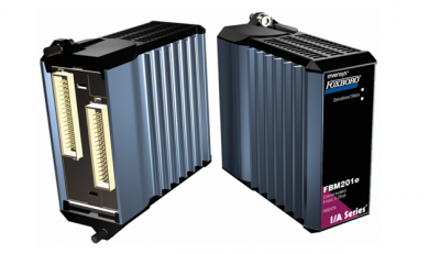
FOXBORO FBM201e Analog Input (0 to 20 mA) Interface Modules
FOXBORO FBM201e Analog Input (0 to 20 mA) Interface Modules
The FBM201e Analog Input Interface Module provides eight dc current input channels.
FEATURES
Key features of the FBM201e module are:
Eight 0 to 20 mA dc channels for input of analog
sensor signals
Each analog input channel is galvanically isolated
from other channels and ground
Compact, rugged design suitable for enclosure in
Class G3 (harsh) environments
Execution of an analog input application program
that provides conversion time and configurable
options for integration time and Rate of Change
Limits
High accuracy achieved by sigma-delta data
conversions for each channel
Termination Assemblies (TAs) for locally or
remotely connecting field wiring to the FBM201e
Termination Assemblies for per channel internally
and/or externally loop powered transmitters.
OVERVIEW
Each FBM201e Analog Input Interface Module
contains eight analog input channels, each channel
accepting a 2-wire, dc input from an analog sensor
such as a 4 to 20 mA transmitter
The modules perform the signal conversion required
to interface the electrical input signals from the field
sensors to the optionally redundant fieldbus.
COMPACT DESIGN
The FBM201e module has a compact design, with a
rugged extruded aluminum exterior for physical
protection of the circuits. Enclosures specially
designed for mounting the FBMs provide various
levels of environmental protection, up to harsh
environments per ISA Standard S71.04.
HIGH ACCURACY
For high accuracy, the module incorporates sigma
delta data conversion on a per-channel basis, which
can provide a new analog input reading every 25 ms,
and a configurable integration period to remove any
process noise and power-line frequency noise.
Each time period, the FBM converts each analog
input to a digital value, averages these values over
the time period, and provides the averaged value to
the controller.
EASY REMOVAL/REPLACEMENT
The module can be removed/replaced without
removing field device termination cabling, power or
communications cabling.
VISUAL INDICATORS
Light-emitting diodes (LEDs) incorporated into the
front of the modules provide visual status indications
of Fieldbus Module (FBM) functions.
MODULAR BASEPLATE MOUNTING
The module mounts on a modular baseplate (see
Figure 1) which accommodates up to four or eight
FBMs. The modular baseplate is either DIN rail
mounted or rack mounted, and includes signal
connectors for redundant fieldbus, redundant
independent dc power, and termination cables.
FIELDBUS COMMUNICATION
A Fieldbus Communication Module or a Control
Processor interfaces the redundant 2 Mbps module
Fieldbus used by the FBMs. The FBM201e module
accepts communication from either path (A or B) of
the redundant 2 Mbps fieldbus – should one path fail
or be disabled at the system level, the module
continues communication over the active path.
TERMINATION ASSEMBLIES
Field I/O signals connect to the FBM subsystem via
DIN rail mounted TAs (see Figure 1). The TAs used
with the FBM201e module are described in
“TERMINATION ASSEMBLIES AND CABLES” on
page 7
FUNCTIONAL SPECIFICATIONS
Process I/O Communications
Communicates with its associated FCM or FCP via
the redundant 2 Mbps module Fieldbus.
Input Channels
8 isolated and independent channels
Input Range (each channel)
0 to 20 mA dc
Input Channels (8)
ANALOG ACCURACY (INCLUDES LINEARITY)
±0.02% of span
Accuracy temperature coefficient: ±50 ppm/ºC
FIELD DEVICE CABLING DISTANCE
Maximum distance of the field device from the
FBM is a function of compliance voltage @20 mA
(21.4 V dc), wire resistance, and voltage drop at
the field device.
Input Channel Isolation
Each channel is galvanically isolated from all other
channels and earth (ground). The module/TA
withstands, without damage, a potential of 600 V ac
applied for one minute between any channel and
ground, or between a given channel and any other
channel.
WARNING
This does not imply that these channels are
intended for permanent connection to
voltages of these levels. Exceeding the limits
for input voltages, as stated elsewhere in this
specification, violates electrical safety codes
and may expose users to electric shock.
Power Requirements
INPUT VOLTAGE RANGE (REDUNDANT)
INPUT CHANNEL IMPEDANCE
61.5 Ω nominal
INPUT SIGNAL A/D CONVERSION
Each channel performs A/D signal conversion
using an independent Sigma-Delta converter.
INTEGRATION PERIOD
Software configurable.
COMMON MODE REJECTION
>100 db at 50 or 60 Hz
NORMAL MODE REJECTION
>95 db at 50 or 60 Hz
LOOP SUPPLY
24 V dc ±2.5%
OUTPUT IMPEDANCE
68 Ω
LOOP POWER SUPPLY PROTECTION
Each channel is channel-to-channel galvanically
isolated, current limited, and voltage regulated.
All analog inputs are limited by their design to less
than 30 mA. If the current limit circuit shorted out,
the current is limited to about 100mA.
24 V dc +5%, -10%
CONSUMPTION
7 W (maximum)
HEAT DISSIPATION
3 W (maximum)
Calibration Requirements
Calibration of the module and termination assembly is
not required
FUNCTIONAL SPECIFICATIONS (CONTINUED)
Regulatory Compliance
ELECTROMAGNETIC COMPATIBILITY (EMC)
European EMC Directive 89/336/EEC
Meets: EN 50081-2 Emission standard
EN 50082-2 Immunity standard
EN 61326 Annex A (Industrial
Levels)
CISPR 11. Industrial Scientific and Medical
(ISM) Radio-frequency Equipment –
Electromagnetic Disturbance Characteristics – Limits and Methods of Measurement
Meets Class A Limits
IEC 61000-4-2 ESD Immunity
Contact 4 kV, air 8 kV
IEC 61000-4-3 Radiated Field Immunity
10 V/m at 80 to 1000 MHz
IEC 61000-4-4 Electrical Fast
Transient/Burst Immunity
2 kV on I/O, dc power and communication
lines
FBM201e
FBM201e